Reverse-Forward of 3-Phase Motor using DOL Starter – Wiring, Power & Control Circuit
How to REV-FWD a 3-Phase Motor Using DOL Starter? (2 Directions, 1 Speed)
The reverse forward motor control operation is used to operate a three-phase motor in both forward and reverse directions. This type of control is commonly used in industrial and commercial applications where there is a need to change the direction of rotation of a motor.
The reverse forward motor control operation can be achieved using various methods, including using a contactor and relay. In this article, we will discuss the reverse forward motor control operation of a three-phase motor using direct-on-line (DOL) starter based on two contactor and a relay.
Table of Contents
Working of the Circuit
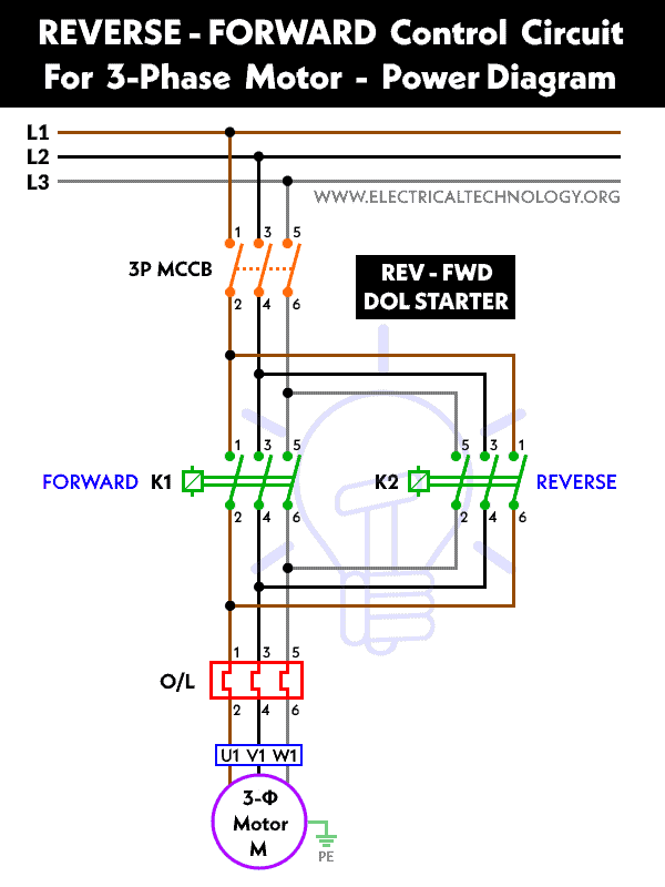
The reverse forward direction of a motor can be achieved using two contactor (K1 & K2) and relay. The K1 contactor is used to switch the three-phase power supply to the motor and run in clockwise direction. The K2 contactor is used to run the motor in anti-clock wise direction. The relay is used to control the direction of rotation i.e. it changes the two lines supply out of three lines to the motor which is must to use for changing the direction of rotation of the motor.
When the forward operation contacts of the relay are energized, they close, and the contactor K1 is activated, causing the motor to run in the forward direction. The three-phase power supply (via L1, L2 & L3) is applied to the motor’s U, V, and W terminals, causing the motor to rotate in the clockwise direction.
When the reverse operation contacts of the relay are energized, they close, and the normally closed auxiliary contact of the contactor opens. This activates the reverse contactor K2 coil, causing the motor to run in the reverse direction. The three-phase power supply is now applied to the motor’s W, V, and U terminals, causing the motor to rotate in the counterclockwise direction.
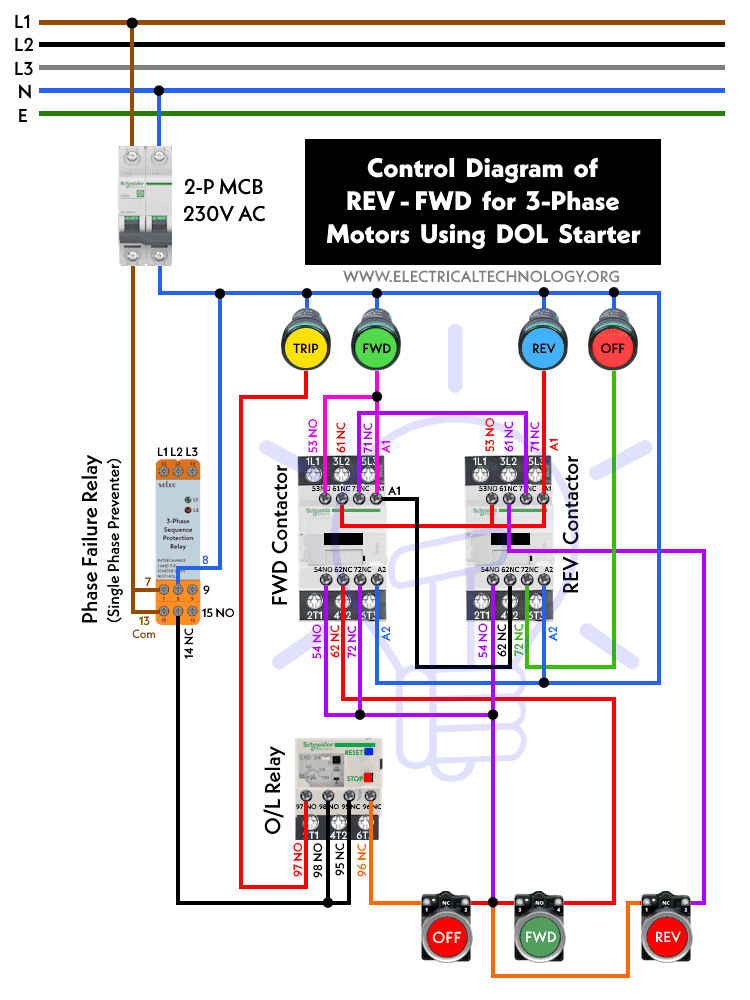
The control circuit of the contactor and relay can be connected to a control device such as a switch or a PLC to control the direction of the motor. When the switch or PLC provides a signal to the control circuit, it energizes the corresponding operation contacts of the relay, causing the motor to run in the desired direction.
The following are the wiring, power, and control circuit diagrams used to change the direction of the motor in clockwise and counterclockwise (anti-clock) directions.
- Reverse-Forward Star/Delta Starter for Three Phase Motor using Timer
- Star-Delta Starter for Reverse – Forward Operation Without Timer
Wiring, Power & Control Diagrams of Reverse & Forward Operation
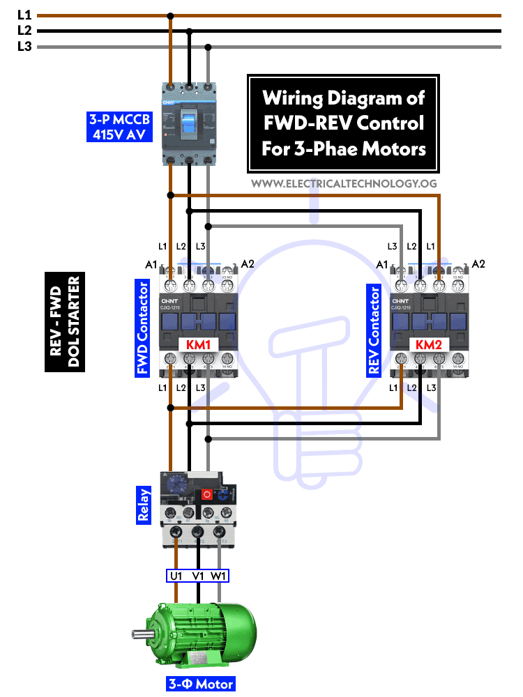
Schematic Wiring Diagram
Power Diagram:
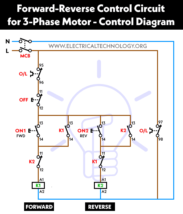
Control Circuit Diagram:
Control Wiring Diagram:
Abbreviations:
- O/L = Over Load Relay
- NO = Normally Open
- NC = Normally Close
- REV = Reverse
- FOR = Forward
- K1 = Right Direction – Forward Contactor
- K2 = Left – Direction Reverse Contactor
How to Reverse a 3-Phase Motor Using DOL Starter?
- Install a contactor with a suitable rating for the motor’s power and voltage rating. The contactor should have three main terminals for the three-phase power supply (L1, L2 & L3) and three auxiliary contacts for control circuits.
- Install a relay with two sets of contacts, one for forward operation and the other for reverse operation. Connect the relay to the control circuit of the contactor.
- Connect the three phase power supply (400V to 480V) to the main terminals of the contactor. Connect the motor to the output terminals of the contactor.
- Connect the forward operation contacts of the relay to the control circuit of the contactor. Connect the reverse operation contacts of the relay to the control circuit of the contactor, with the reverse contacts in series with a normally closed auxiliary contact of the contactor.
- When the forward operation contacts of the relay are energized, the contactor will be activated and the motor will run in the forward direction. When the reverse operation contacts of the relay are energized, the contactor will be activated and the motor will run in the reverse direction.
- To reverse the motor, you need to energize the reverse operation contacts of the relay, which will open the normally closed (NC) auxiliary contact of the contactor and activate the reverse contactor coil, causing the motor to run in the opposite direction.
- You can control the operation of the motor by connecting the control circuit of the contactor to a suitable control device, such as a switch or a PLC, that can provide the necessary signals to activate the forward or reverse operation contacts of the relay.
Applications of REV-FWD Operation of Motors
The reverse forward operation of a three-phase motor has several applications in various industries, including:
- Conveyor systems: Conveyor systems are widely used in industries for material handling. The reverse forward operation of a three-phase motor is used to control the movement of the conveyor in both forward and reverse directions.
- Cranes and hoists: Cranes and hoists are used for lifting and moving heavy loads. The reverse forward operation of a three-phase motor is used to control the direction of rotation of the motor, which controls the movement of the crane or hoist.
- Pumps and compressors: Pumps and compressors are used to move fluids and gases in industrial applications. The reverse forward operation of a three-phase motor is used to control the direction of rotation of the motor, which controls the flow direction of the fluid or gas.
- Machine tools: Machine tools such as lathes, milling machines, and drilling machines require the motor to operate in both forward and reverse directions. The reverse forward operation of a three-phase motor is used to control the direction of rotation of the motor, which controls the operation of the machine tool.
- Fans and blowers: Fans and blowers are used for ventilation and air movement in various applications such as HVAC systems and industrial processes. The reverse forward operation of a three-phase motor is used to control the direction of rotation of the motor, which controls the direction of the airflow.
Advantages of Basic REV-FOR Operation of Motors
- The reverse forward motor control operation has several advantages, including:
- It allows the motor to be operated in both forward and reverse directions, making it versatile and flexible.
- It provides a simple and cost-effective way of controlling the direction of rotation of a motor.
- It is easy to install and requires minimal maintenance.
Summary:
The reverse forward motor control operation using a contactor and relay is an effective way of controlling the direction of rotation of a three-phase induction motor. It provides a simple and cost-effective solution for industrial and commercial applications that require the motor to be operated in both forward and reverse directions. By following the steps outlined in this article, you can easily achieve the reverse forward motor control operation using a contactor and relay.
Related Motor Control & Power Diagrams:
- Automatic Star-Delta Starter using Timer – Power, Control & Wiring Diagrams
- STAR/DELTA Starter Without Timer – Power, Control & Wiring Diagrams
- Starting & Stopping of 3-Phase Motor from More than One Place – Power & Control Diagrams
- Controlling of 3-Phase Motor from More than Two Places – Power & Control Diagrams
- Automatic Sequential Motor Control Circuit – Power & Control Diagrams
- Reverse / Forward Circuit for 3-Phase Motors – Power & Control Diagrams
- Three Phase Slip Ring Rotor Starter – Control & Power Diagrams
- Multispeed (2 Speeds, 2 Directions) 3-Phase Motor Power & Control Diagrams
- Multispeed (2 Speeds, 1 Direction) 3-Phase Motor Power & Control Diagrams
- Multispeed (3 Speeds, 1 Direction) 3-Phase Motor – Power & Control Diagrams
- What is Motor Starter? Types of Motor Starters and Motor Starting Methods
- What is Soft Starter? Its Working, Diagram and Applications
- Direct Online Starter – DOL Starter Wiring Diagram for Motors
- What is a Contactor ? Types, Working and Applications
- Why Do We Need to Install a Starter with a Motor?
- Three Phase Motor Power & Control Wiring Diagrams
